GUIDES NOT INCLUDED
Keep calm and press the space bar
The Complete Beginner's Completely Incomplete Guide to Oxygen Not Included
PIPES AND PUMPS: LIQUID AND GAS FLOW BASICS
Introduction
There are some things that are useful to know about liquid and gas piping. Which, through a stroke of extraordinarily good fortune, is exactly what this section is about.
First we cover the different kinds of pumps there are, then how much liquid or gas can be pumped into a tile (or an area) and finally - and perhaps most importantly - how to control liquid (and gas) flow.
A bathroom and SPOM setup is used as an example for how controlling liquid flow can be done and why it is useful to know how to do..
Liquid and gas pumps
For liquids as well as for gases there is a large pump and a small (called "mini") pump. All pumps are unlocked through research.
The large pumps are built with metal ore, making them easy to build early on. The small pumps require plastic.
Pumps, even liquid pumps, do not need to be built on a foundation. Meaning you can build a liquid pump in the middle of a body of liquid and it will still work.

Liquid pump

Mini liquid pump

Gas pump

Mini gas pump
Pumps pump so-called packets, of either liquid or gas. Each packet can only contain one type of liquid or gas, not a mix of different kinds.
You can see the packets using the plumbing overlay and the ventilation overlay, the icons for them are in the top right. Each section of pipe contains (or can contain) one packet.
Something to keep in mind is the ratio of how much a pump can pump compared with how much can fit in a packet, meaning in a section of pipe.
-
A liquid pump can pump 10kg of liquid per packet
-
A liquid pipe can contain 10kg of liquid per packet
In ideal conditions, meaning the liquid pump only has one type of liquid to pump and there is enough of that liquid, liquid pumps and liquid pipes have a 1-to-1 ratio: one pump will completely fill a liquid pipe.
-
A gas pump can pump 0,5kg (500g) of gas per packet
-
A gas pipe can contain 1kg (1000g) of gas per packet
This means that a gas pipe packet can fit the output of two gas pumps. (As long as they are the same kind of gas.)

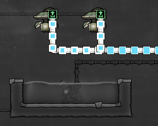
One liquid pump can fill a liquid pipe. Gas pipes can fit the output of two gas pumps (as long as they are the same kind of gas).
Vents and gas pressure: how much gas can fit in a tile?
Somewhat counter-intuitively, when you are pumping gases it isn't the gas pump that determines how much gas can be pumped into an area. Rather, that is determined by the gas vent.
-
The gas vent can vent up to 2kg per tile of gas into an area
-
The high pressure gas vent can vent up to 20kg per tile
The size of the pump - gas pump or mini gas pump - will only affect how quickly gas is pumped, not how much can be pumped into an area.

Gas vent. Can vent up to 2kg per tile

High pressure gas vent. Can vent up to 20kg per tile
Geysers that emit gases have something in common with vents in that they also have an upper pressure limit regarding their ability to emit gas.
-
At 5kg per tile of gas the area becomes over-pressurized and the geyser stops emitting gas.

The gas pressure is 5kg per tile, meaning the natural gas geyser will not emit more gas.
This means that if you want to maximize the amount of gas gathered from a geyser, you need to pump the gas into a different area (or room) using a high pressure gas vent. This way you can fit 20kg of gas per tile rather than 5kg.

These rooms are the same size but the one on the right can contain four times as much gas. The natural gas geyser over-pressurizes at 5kg per tile, while the high pressure gas vent can keep going until the area reaches 20kg of gas per tile.
This approach can be taken even further, if you don't mind bending the laws of physics a bit. You can have double layers of gas on a tile: you can have gas in a reservoir as well as gas in the tiles the reservoir is built on. (That was a confusing explanation - see picture below.)
This means you can fill your gas storage room with gas reservoirs. Then pump gas through the reservoirs and out a high pressure gas vent in the room. Then the room will first fill up with 20kg per tile of gas, after which the gas reservoirs will start filling up. They can hold 5kg each.
(Rocket gas storage tanks can hold even more gas. I don't use them for this, but have read of people storing lots of gas in their base using rocket modules.)

Min-maxing gas storage. The gas storage room is full of gas, and there are a bunch of gas reservoirs that can hold additional gas.
If you build one of these, remember to also put a separate gas pump in the gas storage room, to pump gas to wherever you need it.
(You can add automation to make sure the pumps only kick in if there is enough gas - as covered in the section on automation.)
As a final note: this approach slightly bends the laws of physics. If you don't mind breaking those laws entirely, you can also set up an infinite gas (or liquid) storage area. I don't use that mechanic myself, but you can find guides for it online. Search for infinite gas storage or infinite liquid storage.
Vents and liquid pressure: how much liquid can fit in a tile?
Unlike the gas vent that has two kinds of vents, there is only one liquid vent.
It will stop working - stop letting out liquid - if or when the pressure on its tile reaches 1000kg.

Same weight, different volume. Each section has 10000kg of liquid. Different liquids take up different amounts of space.

Overpressure. The polluted water vent will not emit more polluted water.

Liquid vent.
Stops venting at 1000kg of pressure.
To make things a bit more complicated, the amount of liquid that can fit in a tile varies depending on what kind of liquid it is.
Some of the more common liquids and how much is required to fill a tile:
-
Petroleum: 740kg
-
Crude oil: 870kg
-
Water: 1000kg
-
Polluted water: 1000kg
-
Ethanol: 1000kg
-
Salt water: 1100kg
-
Brine: 1200kg
Note: The liquid vent will stop working at 1000kg of pressure, regardless of what kind of liquid is being pumped. But: not all liquids will necessarily reach that amount of pressure. For instance petroleum and crude oil won't block a liquid vent even when a tile is completely immersed.
(To stop such a vent you can use automation, e.g. by connecting a hydro sensor to the vent to close it when a tile is filled.)
A tile can contain more liquid than is listed in the bullet points above if there is pressure on the tile. One such example is your water storage area. Mouse over the tiles in the upper and lower sections of it and you will probably notice a difference in water volume per tile.
Liquid vents, like gas geysers, can over-pressurize and stop emitting liquid. I haven't done any testing on it, but this generally seems to happen when a vent is in three tiles of liquid (above its neutronium base) and the third tile is at 500kg per tile.
Leaky oil fissures will over-pressurize and stop emitting oil, but oil reservoirs (if I recall correctly) will not. They can keep producing oil even when completely submerged. (But they aren't a geyser, so they need water and power - and occasional depressurizing - to work. See the section on Getting oil, petroleum and plastic for more on oil wells.)
Liquid and gas piping basics: inputs and outputs
[I'll add this section soonish, but for now you can find the basics covered in: The early game.]
Controlling packet flow


Liquid bridge. Liquid flows in the direction of the arrow. From white to green in the plumbing overlay.
Pumps and pipes do a decent job of acting like you would want them to, but at times they need a bit of help. If your liquid (or gas) isn't flowing in a pipe, it might be because it doesn't know which direction to go.
(Note: another reason liquid might not be flowing is if you connected your inputs and outputs incorrectly. Double-check your plumbing overlay and the white and green bits.)
-
You can use liquid bridges (or gas bridges) to tell the game what direction you want things to flow.
Liquid bridges only allow liquid to flow in one direction across the bridge. That direction is from white to green - from the input port to the output port. (Look closely and you will see a small arrow showing the direction.)
If you ever have liquid that isn't moving even though it seems like it should, try putting in a liquid bridge to show the direction you want liquid to flow.
Let's look at an example where liquid needs a liquid bridge to know what to do.

Above: The liquid stopped because it didn't know which direction to flow.
Below: A liquid bridge forces the liquid to choose a direction to go in.
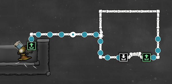
In the example above, liquid will stop flowing once the pump has filled the entire loop. But you can also create loops of liquid that will circulate forever, even if you disconnect them from a pump.
Infinite loops
An infinite loop - a pipe loop where liquid will flow around and around forever - can be useful for instance in cooling loops.
To turn the above design into an infinite loop, first disconnect the loop.

The water in the loop will be still - it won't circulate. That is because the pipes are so full the liquid cannot move. All you have to do to get it moving is to remove one packet of liquid.
You can do this either with the Empty Pipe command (bottom right, but using it requires you to have a dupe with the plumber skill) or you can simply deconstruct one section of pipe and then rebuild it.
When done, the liquid in the loop will start circulating, and will continue circulating forever.
You can also build an infinite loop without the need for emptying or deconstructing pipes. To do this, use a liquid bridge to connect to your loop.
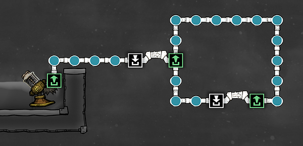
A liquid bridge will only allow liquid to pass over it if there is an empty space for it on the other side of the bridge. Meaning liquid bridges are very useful for making sure pipes, or constellations of pipes, won't over-fill.
In the picture above (though you can't see movement in a static picture - sorry about that), the liquid leading up to the loop is still, and the liquid in the loop is circulating.
If this was poorly explained, try building something like the picture above for yourself. It's a really useful mechanic and definitely worth getting comfortable with building.

Infinite loops. In the upper middle section is an anti entropy thermo-nullifier that produces chill. On either side there are liquid loops used to help distribute that chill across the sleet wheat farm. (You can't see it in the picture, but the liquid keeps circulating. For ever and ever.)
Using liquid bridges to prioritize liquid sources
The liquid bridge is useful not just for forcing liquid to choose a direction, but also for prioritizing liquid (or pipe) sources.
You will come across times when you want to be able to prioritize which pipe to use. For instance to tell the game: if there is liquid in this pipe, use it first.
The liquid bridge, once again, is our friend here. There are two ways to use it: the input and the output side.
The output side, the green bit, can be used as was described in the previous part about creating (but not overfilling) infinite loops. The mechanic is:
-
Liquid flowing along a liquid bridge that connects onto a normal pipe will only enter the pipe if there is space.
This mechanic can also be used for instance when feeding water to a SPOM, where you might occasionally want to use water from one source, like bathroom overflow water, and otherwise use a different source. (This example is pictured at the end of this section.)
Then there is the input side, the white bit:
-
When liquid comes to a liquid bridge, it will always try to cross over the liquid bridge first.
Only if that is not possible - if the pipe on the other side is full - will it use a different pipe.

Liquid bridges. The liquid bridge will only let water from the pump through if there is space on the pipe. The pump in the picture is a back-up, secondary source that makes sure the pipe stays full.

Liquid bridges. The middle tank will fill up first, and only when there is no space in the pipe to the middle tank will water start flowing to the upper tank.
This mechanic is useful in many different kinds of situations. Two common examples:
-
It is used as an overflow mechanism for a bathroom decontamination setup.
-
It is used as an overflow mechanism for excess hydrogen in a SPOM.
Example setup: bathroom, SPOM and water source
I'll conclude with an example of how liquid bridges can be used in combining various systems. This example is (a simplified version of) something I build in pretty much every playthrough: sending excess water from bathrooms to a SPOM.

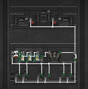
Prioritizing flow. Excess water from a bathroom water decontamination setup is sent to a SPOM. (The piping here isn't complete - check the last picture for the final version.)
In the pictures above, there is a polluted water decontamination setup in the middle. (How that setup works, and how to build one, is covered elsewhere in the guide: see Recycling bathroom water.)
Newly decontaminated water is first sent back into the bathroom loop. This is done using a liquid bridge - seen on the far right in the middle of the picture - that tells the water to go down if there is space in the pipes below.
Since bathrooms produce more liquid than they use, the bathroom and decontamination setup will produce excess water. When the pipe going down from the liquid bridge is full, any excess water will be sent up to the SPOM.
(A SPOM is a setup that produces oxygen. It is covered later in the guide: see Oxygen: to know the SPOM is to love the SPOM.)
We aren't quite done yet. With a setup like the one pictured above, the SPOM would only get water sporadically, whenever there was excess from the bathroom.
We want to add a way to make sure the SPOM always gets water. We can do this by adding a pipe from another water source. (If you're running low on water, see Getting (more) water.)

Almost there. The liquid bridge connecting the water supply to the SPOM means it will only use water from the water supply if the pipe from the bathroom is empty. However, it will pump water both to the SPOM (good) and to the bathroom (bad).
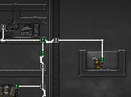
All set. An additional liquid bridge stops the water supply pump from pumping water to the bathroom.
In the picture above a liquid bridge is used to make sure the SPOM uses the excess bathroom water first, and only uses water from our water pump when there is no excess water from the bathroom.
(Bathrooms don't produce that much excess water, and SPOMs use quite a bit of water. So you don't actually need to use a liquid bridge here. Even if your SPOM uses both your bathroom excess water and your water source evenly, it isn't likely to clog up your bathroom. But if your bathroom water clogs up, you will have accidents. So adding extra safety mechanisms to avoid that, even if they are probably unnecessary, is a good idea.)
We're almost done, but there is still one problem with this design. In the picture above, water from our water source would be pumped both to the SPOM and to our bathroom. That would clog up the bathroom and lead to accidents.
We want to make sure that the water pumped from our water supply is used only for the SPOM, not our bathrooms. This can be done by adding another liquid bridge to the design, to stop water from flowing from our water source to our bathroom.
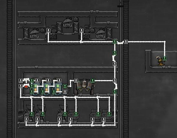
Bathroom and SPOM. This is a simplified depiction of something I use in pretty much every playthrough. Excess water from bathrooms (and showers, polluted water dumping stations, etc.) is sent to a SPOM. The SPOM will also need an additional water source. Liquid bridges are used in various locations to control the flow of liquid.